AUTOMATIC WATER LEVEL CIRCUIT
Do It Yourself À U Solder Kit
Designed by LES BANKI & given away to the public.

Welcome to the Instructions for the
Automatic Water Level Circuit
Please read our terms & conditions before proceeding. Thank You.
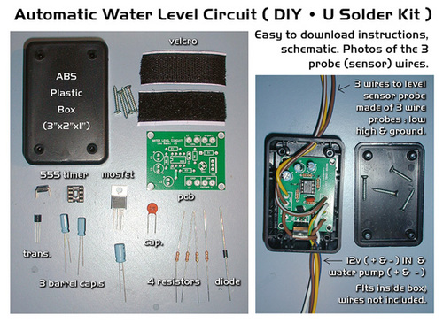
| Automatic Water Level Circuit À PARTS LIST | |||
|---|---|---|---|
QUANTITY |
CODE# |
PART# |
DESCRIPTION |
1 |
IC1 |
LM555, bipolar or CMOS |
555 timer chip, 200ma |
1 |
IC1-SOCKET |
8 PIN SOCKET |
8 pin IC socket |
2 |
* R1- R2 |
1M ohm, 1/4 watt Resistor | Resistors (brown•black•green) |
2 |
R3 - R4 |
10K ohm, 1/4 watt Resistor | Resistors (brown•black•orange) |
2 |
C1 - C2 |
1uf , 50 volt Capacitor | smaller blue barrel |
1 |
C3 |
0.1uf Ceramic Capacitor | orange |
1 |
C4 |
100uf , 50 volt Capacitor | larger blue barrel |
1 |
D1 |
N4007 - Diode | Diode (black) |
1 |
TR1 |
BC547 Transistor | small black 3 prong Transistor |
1 |
TR2 |
MTP3055 Mosfet | MOSFET |
1 |
PCB |
PCB board | Green |
1 |
BOX |
Black Box (3" x 2 "x 1 " ) | Black |
4 |
Screws |
#2 screws, .3" long | silver |
1 |
- |
VELCRO hook & pile | Black |
2 |
* R1 - R2 |
510K ohm, 1/4 watt Resistor | Resistors (green•brown•yellow) |
| * R1 - R2 - either use two 1M for R1 & R2 with a 0 - 10% solution of electrolyte, or use the two 510K ohm value resistors for a heavy 20% by weight Electrolyte solution. Read more down below in the instructions | |||
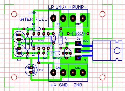
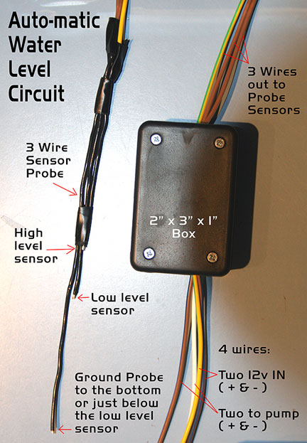
Circuit description for " Automatic Water Level Sensor & Pump Driver Circuit" I designed this circuit for automatic re-fill of electrolyzers in ‘water fuel’ systems. However, it can be adapted to many other uses as well. Despite looking deceptively simple, it is quite ‘sophisticated’. In brief: The task itself is simple. We have a vessel (tank/container) we wish to fill automatically, between pre-determined minimum and maximum levels, as set by the probes. We found solid copper teflon coated wire (16 gauge), worked well for the 3 probe wires, Initial condition: the pump is required to start automatically if the vessel is empty (or the level is below the required minimum) when the circuit is powered up for the first time. When the HIGH level probe is reached, the pump must STOP. IF the tank/container is already FULL when power is first applied, NOTHING should happen. When your circuit is finished and your probes are in place in your hydrogen cell. Fill your water tank with water, and fill your cell with the circuit plug in or turned ON. *Note this circuit is always ON or OPEN. WHen you apply 12v to the 2 IN wires the" pump motor" or "gravity feed solenoid switch" should start filling your cell. As soon as the water level touches the high level probe, the pump stops. The water pump should NOT turn on again until the level of water reaches the low level probe tip. * Note : This circuit comes with 2 sets of resistors R1 and R2, it was designed for water with a approx. 0% to 10% electrolyte mix. with the change of R1 and R2 to 510K ohms for 20% solution of electrolyte commonly NaOH or KOH, by weight measured to 100% water by weight. In greater detail: The circuit is based on a 555 IC (Bipolar or CMOS) for sensing the minimum and maximum water levels and turns a MOSFET on/off which directly controls a 12V DC pump motor. As the detailed operation of the 555 is explained in numerous publications, there is no point repeating it here. Suffice to say that here we are using the ‘Trigger’ and ‘Threshold’ pins (2 & 6) to detect the maximum and minimum levels, respectively. The two voltage comparator op-amps inside the 555 control the output, turning it on/off.. Looking at the circuit diagram you will notice that the ‘Trigger’ pin (2) is marked ‘HIGH probe’, despite being triggered (output goes HIGH) when the voltage drops below 1/3 of the supply voltage and, the ‘Threshold’ pin (6) is marked ‘LOW probe’ while it is ‘reset’ (output goes LOW) when the voltage rises above 2/3 of the supply voltage. If this appears to you as being upside-down, IT IS! The circuit works as follows: Three (3) probes are immersed in the vessel. (usually from the top) Now suppose the vessel is EMPTY. Resistors R2 and R1 (1M) tie the ‘Trigger’ and ‘Threshold’ pins (2 & 6) to the positive (+) rail (supply). In other words, both pins are HIGH. Remember (from above), to make the output of IC1 go HIGH, the trigger pin (2) needs to drop below 1/3 of the supply voltage. (4V with a 12V supply) We need to fill the vessel when IC1’s output is LOW. TR1 is OFF. The GATE of the MOSFET switch (TR2) is connected to the supply rail (+12V) with R4 (10k). TR2 is thus turned on and the pump motor is running. TR1 (BC547) is connected between the IC1s output (pin 3) and the TR2’s GATE. Now, back to the condition when the IC1’s output is low, TR2’s GATE is HIGH (+12V) and conducting. The pump is operating and water is being filled. As the water level rises, a water ‘bridge’ is formed between the GROUND (common) probe and the ‘LOW probe’ (Threshold, pin 6) This ‘bridge’ constitutes a low resistance, relative to the high resistance of R2 (1M), bringing the voltage at this pin to a low level (at least below 1/3 supply but actual voltage depend on the conductivity of the water). However, this is IGNORED by IC1 since its output is already LOW (in the ‘reset’ mode) When the water level reaches the ‘HIGH probe’, a water ‘bridge’ is formed between it and the GROUND probe. Just as with the LOW probe, this ‘bridge’ constitutes a low resistance, relative to the high value of R1 (1M), bringing the trigger voltage to below the required level (1/3 supply voltage) and IC1 triggers, its output going HIGH. Now Tr1 is turned on, the bias voltage/current of TR2 is removed and the pump STOPS. The filling cycle is completed. The emptying cycle is as follows: As the water level falls, the ‘shorting’ water ‘bridge’ between the GROUND probe and HIGH probe (‘Trigger’, pin 2) is removed and the voltage rises above the 1/3 supply level (+4V). Once the water level drops below the LOW probe (‘Threshold’, pin 6), the ‘shorting’ water ‘bridge’ disappears and the voltage rises to 2/3 supply voltage (8V), IC1 ‘resets’. (its output goes LOW) To simplify: Capacitors C1 and C2 (1uF), together with resistors R1 and R2 form an approx. 1 second time delay. When selecting Bipolar or CMOS for this circuit, keep in mind that the 3 voltage divider resistors inside the 555 have very different values: 5k for the Bipolar and 100k for CMOS. Since the ‘water bridge(s)’ between the relevant probes and R1 & R2 (1M) are forming voltage dividers, it should be obvious that the internal voltage dividers resistor values ought to be considered. By removing the “phase reversing stage [simple modification: omit TR1 (BC547) and R4 (10k), replace R3 (10k) with 22 ohms and connect it directly to the Gate of TR2 (MOSFET)] this versatile circuit can also be used in reverse. It can activate a pump when the vessel/container is full (in order to empty it or transfer its contents to another container) and stop it when the desired minimum level is reached. In this case, note that when power is applied to the circuit for the first time and the vessel is not full, the pump starts up briefly. (due to the time constant of R2/C2, apron. 1 sec.) As stated above, this circuit (as presented) was designed to drive 12V DC pumps directly. "Automatic Water Level Circuit" Schematic Les Banki (Electronic Design Engineer) |

Thank you for your time, enjoy reading all you can on the subject.
It is vital to our future. Running lean and green, with mr green jeans.
Looking for some Good Men to Drive Lean Sorry for the un-controllable humor, I laughed so |
|

 Ortho Hydrogen the only way to go!
updated - 5/ 21/2014
About / Awareness / Education / HG store / Terms of HG / Contact / Links / Sponsor
Hydrogen Garage LLC • California • USA