DIY DUAL O2 SENSOR FUEL SAVER (EFIE)
Do It Yourself · U Solder Kit
(Electronic Fuel Injection Enhancer)
Designed by "electrojolt"

Welcome to the Instructions for the
DIY Dual Oxy Sensor Fuel Saver Circuit
Please read our terms & conditions before proceeding. Thank You.
New VOLO performance Gas Saving Circuit - Volo FS3
| "DYI Dual O2 Sensor Fuel Saver Circuit"
This circuit uses one LM324 is a Quad Amplifier. this circuit uses 2 amps per O2 sensor, so it will work to adjust two O2 sensors. As in the photo above, the top half of the circuit board controls the #1 O2 sensor and the bottom half controls the #2 O2 sensor.
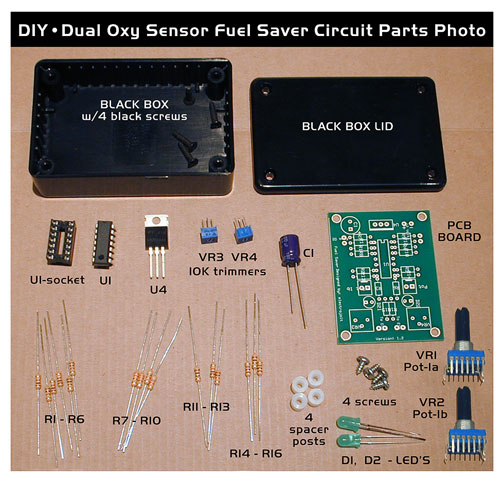
Well, you need the parts shown on the schematic, soldering iron, solder, wires, multi-meter, the usual stuff to build small electronic circuits. The multi meter can be attached with velcro to the dashboard for a temporary voltage monitor. Yes you will need to CUT the O2 sensor wire, so the wire from the O2 sensor connects to the input of the circuit and the output of the circuit connects to the ECU or ECM The circuit needs to be adjusted once it is installed under your dash board. Easy to do with a Multi meter. Locate all the components : |

| DIY Dual Oxygen Sensor Fuel Saver Circuit · PARTS LIST | |||
|---|---|---|---|
QUANTITY |
CODE# |
PART# |
DESCRIPTION |
1 |
U4 |
LM7812 |
12 volt Voltage Regulator |
1 |
U1 |
LM324 |
Quad OP AMP |
1 |
U1-SOCKET |
14 PIN SOCKET |
14 pin IC socket |
6 |
R1- R6 |
100 ohm, 1/4 watt Resistor | Resistors (brown•black•brown) |
4 |
R7 - R10 |
1M ohm, 1/4 watt Resistor | Resistors (brown•black•green) |
2 |
R11, R12 |
330 ohm, 1/4 watt Resistor | Resistors (orange•orange•brown) |
2 |
R13, R14 |
1K ohm, 1/4 watt Resistor | Resistors (brown•black•red) |
2 |
R15, R16 |
4.7K ohm, 1/4 watt Resistor | Resistors (yellow•violet•red) |
* either 2 |
VR1, VR2 |
1K Potentiometer, Pot.1A & 1B | Audio Potentiometer |
* or 1 |
VR1 & 2 |
1K DUAL Potentiometer, 1A & 1B | Dual Audio Potentiometer |
2 |
VR3, VR4 |
10K Variable Potentiometer | Trimmer pots (blue) |
2 |
D1 , D2 |
LED lights | Green |
1 |
C1 |
100uf , 50 volt Capacitor | blue barrel |
1 |
PCB |
PCB board | Green |
1 |
BOX |
Black Box ( 2.19" x .83"x 3.3" ) | Black |
4 |
Screws |
#4 screws, .3" long | silver |
4 |
Spacers |
.25" x .25" x #4 hole | Natural |


There are 3 Ways Different Combos of the Dual O2 Sensor Circuit. Pre 1987 carbureted cars don't have Engine Control Management Systems 1) Pre and Post O2 sensors OBD II (most common hook up) You will use the 2 dual pots provided and use both sides of the circuit. One will dial in the first O2 sensor (Pre-catalytic converter) & the 2nd O2 sensor after the catalytic converter (Post-catalytic converter) The 2 different sensors have 2 different voltages. 2) Single O2 sensor OBD I (only one side used) either 1st or 2nd side. 3)Dual exhaust, four O2 sensors, (OBD II) In this install you would need one more DIY Dual O2 Sensor circuits, hooked up both sides 1 & 2, with one dual pot. to control the same voltage for the Pre O2 sensors. The 2nd DIY circuit would be for the Post O2 sensors, adjusting the same signal to both post O2 sensors, using the true feature of a Dual Potentiometer, applying the same voltage resistance to the both PRE and POST sensors. Do It Yourself Dude and start soldering Layout all the resistors first, gold sized bands to the center. The position of the resistors really does not matter, they un-polarized. Don't solder them in until you place the IC socket for U1 Start soldering in the resistors. Add the U1 Quad Op Amp IC chip in later, when the circuit has cooled. You will have to make short jumper (22-24 awg) wires from Pot 1a and 1b from underneath the board to the dual stereo pots. VR1 and VR2. Bend the U4 • voltage regulator 3 pins back as in the photo. The right placement makes the pcb board fit perfect into the box, with 4 corner spacer standoffs on the bottom of the board. Remember to solder the C1 - Capacitor (blue barrel) correctly, the banded side with the shorter wire, is negative and goes into the round hole, the square hole is positive on the Cap. The Cap in the photo below was soldered on wrong, it was later fixed. ( Right when you always thought all square holes meant negative.) That threw me the first time. Always follow the schematic when it comes to components with polarity. Such as the LED lights (D1 & D2 ) they have the shorter cathode wire go into the square hole, The flat side of the LED light on the screen print on top of the pcb board lines up with the tiny notch on the plastic cap of the LED light. The notch is the negative cathode side. Also the Voltage Regulator has to be on right, the photo below is correct.
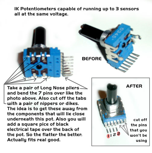
Below shows you how to hook up one of the IK pots in stereo or dual mode for 2 sensors with the same signal control.
|

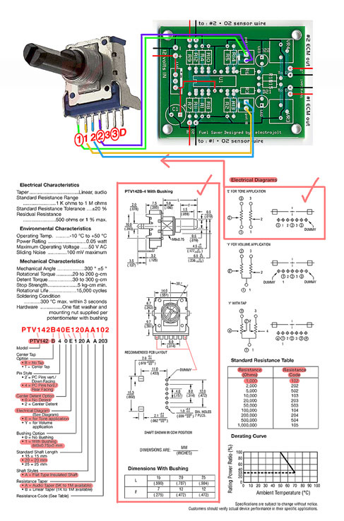
click on diagram to download a larger file.

Print out this template to drill holes in the lid. Click on Template to download a larger file.
While your at the drill press you can drill .25" holes on the side of the box for the 2 power IN wires,
from your ignition (+) and ground (-). Also holes in the side of the box for the 2 wires OUT to the ECM
and 2 wires IN from the oxy sensor signal wire. *Note you must find the (+) signal wire from the group
of wires coming out of you O2 sensor. Some have one, other O2's have 3 wires, even 5 wires.
Some have heaters going to the sensor. A Clymer or Haynes auto manual for your vehicle will tell the
location and color wire to cut and splice into.
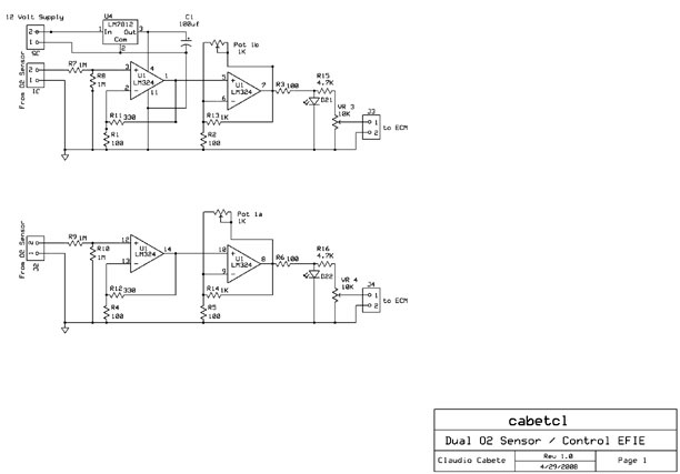
click on Schematic to download a larger file.
How to Adjust the Dual O2 Sensor Control circuit. It is very important that you follow the following steps to adjust the circuit so it will not trigger your check engine light. Once you have the circuit all soldered up and ready to install : Apply one VOLT to the O2 sensor input "J1" ( Your O2 sensor signal wire puts out millivolts under one volt and you can do this adjustment as you install it. Use a Voltage Supply like a "variac.com" type bench voltage generator, to acheve a 1 volt to test the circuit board. Your car's oxy sensor (+) will vary up to one volt. 250mv = lean, 800mv = rich (approx.) Soon we will have instructions on how to take a 1.5" AA battery to do a bench test of applying one volt. If you have the correct size resistor, (approx. 5M resistor) you can get a 1.5 volt battery down to 1 volt, by attaching the resistor to one end of the battery. Then do the adjustment test as written above. Adjust Pot 1b so you have MAX voltage on Output to ECM "J3" Also the LED should light up bright. Adjust VR3 so you have no more than one volt at J3. That is it for this side of the circuit. Now perform the same steps for J2 and J4 and Pot 1a. Note: Pot 1a and Pot 1b is the Mixture adjustment and should be selected according your car needs: If you want to control 2 pre-cat sensors then you should use a dual Potentiometer just like the ones used for Stereo volume control. This way it adjusted both sensors at the same time. If you want to control one pre-cat and one post cat, then 2 1k Potentiometers should be used for Pot 1a and Pot 1b. This way you can adjust the signals separately. If you want to control 2 pre-cats and 2 post cats, then you need 2 circuit build using the Dual Potentiometer in each circuit. This is the instructions for now, more will be added later. ( 9/9/08) ----------------- A good question and answer from customer : Hello Electrojolt ----------------- ------------------- |
Thank you for your time, enjoy reading all you can on the subject.
It is vital to our future. Running lean and green, with mr green jeans.
Looking for some Good Men to Drive Lean Sorry for the un-controllable humor, I laughed so |
|

 Ortho Hydrogen the only way to go!
updated - Dec. 21, 2008 • Back to the Store
About / Awareness / Education / HG store / Terms of HG / Contact / Links / Sponsor
Hydrogen Garage LLC • California • USA